How to Build a PLC Start Stop Circuit (Self-Holding Logic Explained)
In traditional motor control circuits, a self-holding circuit is used to keep a machine running after the start button is released. This is commonly achieved using a contactor auxiliary contact. However, when using a PLC, the same function can be achieved using program logic instead of physical wiring. In this tutorial, we will learn how to create a PLC start stop circuit using ladder logic and function block diagrams. This is one of the most fundamental concepts in industrial automation. We will demonstrate this using a Siemens LOGO! 24V PLC.
PROGRAMABLE LOGIC CONTROLLER (PLC)
ELEKTRECA
3/15/20263 min read
In traditional motor control circuits, a self-holding circuit is used to keep a machine running after the start button is released. This is commonly achieved using a contactor auxiliary contact.
However, when using a PLC, the same function can be achieved using program logic instead of physical wiring.
In this tutorial, we will learn how to create a PLC start stop circuit using ladder logic and function block diagrams. This is one of the most fundamental concepts in industrial automation.
We will demonstrate this using a Siemens LOGO! 24V PLC.
What Is a PLC Start Stop Circuit?
A PLC start stop circuit is a control system that allows an operator to:
Start a machine using a start push button
Stop the machine using a stop push button
Keep the machine running even after releasing the start button
This is known as a self-holding circuit or seal-in circuit.
These circuits are widely used in:
Motor starters
Pump systems
Conveyor belts
Compressors
Industrial machines
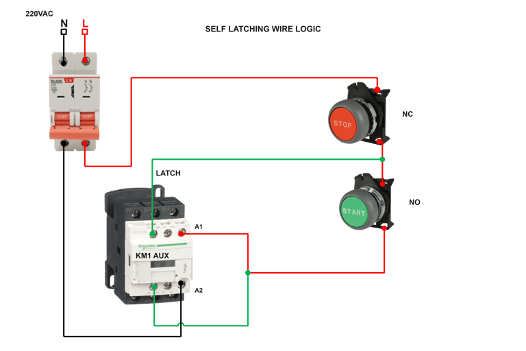
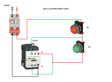
Traditional Self-Holding Circuit (Without PLC)
Before PLCs were widely used, this function was achieved using a contactor auxiliary contact.
Typical components include:
1) Start push button (NO) Starts the machine
2) Stop push button (NC)Stops the machine
3) Contactor Powers the motor
4) Auxiliary contact Maintains the circuit
When the start button is pressed:
The contactor coil energizes.
The auxiliary contact closes.
The circuit remains energized even after releasing the start button.
Pressing the stop button breaks the circuit.
PLC Based Start Stop Circuit
When using a PLC, the auxiliary contact is replaced with program logic.
Instead of wiring a physical seal contact, we use the PLC output as a holding contact in the ladder program.
The PLC receives input signals from the push buttons and controls the contactor.
Components Required
To build this PLC start stop circuit, the following components are required.
1) PLC Siemens LOGO! 24V PLC
2) Start Push Button Normally Open
3) Stop Push Button Normally Closed
4) Contactor Controls the motor
5) Power Supply 24V DC
6) Motor The load being controlled
In this example:
PLC operates at 24V DC
The contactor coil operates at 240V AC
The PLC output relay switches the contactor coil.
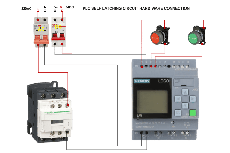
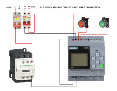
PLC Wiring Diagram
FIGURE 2
The wiring will be as follows.
Inputs
PLC Input
Stop Push Button I1
Start Push ButtonI2
Output
PLC Output
Contactor Coil Q1
The start and stop buttons send 24V DC signals to the PLC inputs.
The PLC output relay then switches 240V AC to the contactor coil.
This allows the PLC to safely control a higher-voltage load.
Ladder Logic Program
The ladder logic for the start stop circuit looks like this.
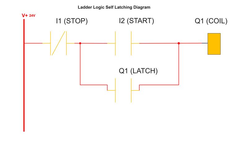
1)Stop contact Normally closed
2)Start contact Normally open
3)Q1 PLC output
4)Q1 contact Self-holding contact
How the Logic Works
Step 1 — System Idle
The stop button is closed, but the start button is open.
Output Q1 is OFF.
Step 2 — Start Button Pressed
Pressing the start button sends a signal to the PLC.
The PLC energizes output Q1.
This energizes the contactor coil, starting the motor.
Step 3 — Self Holding
Once Q1 turns on, the Q1 contact in the ladder logic closes.
This creates a holding path, allowing the output to remain energized even after releasing the start button.
Step 4 — Stop Button Pressed
Pressing the stop button opens the stop contact.
This breaks the ladder logic path and turns OFF Q1.
The contactor de-energizes and the motor stops.
Function Block Diagram
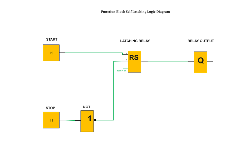
The same logic can also be implemented using Function Block Diagram (FBD).
The structure is:
Start input
Stop input
Latching logic
Output controlling the contactor
Both ladder logic and function block diagrams achieve the same result, but ladder logic is often easier for electricians to understand.
Practical Applications
PLC start stop circuits are used in many industrial systems.
Examples include:
Water pump control systems
Conveyor belt systems
Air compressor control
Industrial motor starters
Automatic machines
Understanding this logic is one of the first steps in learning PLC programming.
Conclusion
A PLC start stop circuit is one of the most important concepts in industrial automation.
By replacing traditional wiring with PLC logic, engineers can create systems that are:
Easier to modify
More reliable
Easier to troubleshoot
More flexible
If you are beginning to learn PLC programming, mastering this circuit will help you understand many more advanced automation systems.

Insights
Connect
david@elektreca.com
+254786927909
© 2026 ELEKTRECA.COM | Privacy Policy | Terms of Service | Disclaimer