Understanding a Pin Relay and Its Base
Relays are essential components in electrical and electronic circuits. They act like remote-controlled switches, allowing a small control signal to turn a much larger load on or off. A pin relay is a relay with clearly defined pins for connection to a base or directly into a circuit board. These pins make installation, replacement, and wiring much easier and more standardised.
CIRCUIT CONTROL DEVICE
ELEKTRECA
5/8/20243 min read
Understanding a Pin Relay and Its Base
Introduction
Relays are essential components in electrical and electronic circuits. They act like remote-controlled switches, allowing a small control signal to turn a much larger load on or off.
A pin relay is a relay with clearly defined pins for connection to a base or directly into a circuit board. These pins make installation, replacement, and wiring much easier and more standardised.
In most control panels, pin relays are mounted on relay bases (also called relay sockets), which provide secure mechanical fixing and electrical connection points for wiring.
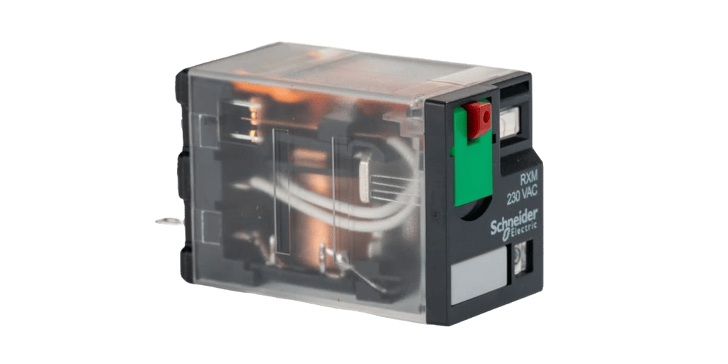
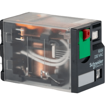
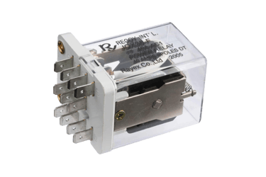
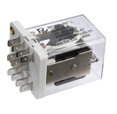
What is a Pin Relay?
A pin relay is an electromechanical switching device that operates using an electromagnet. It has multiple pins (metal terminals) arranged in a standard pattern, each with a specific function — coil terminals, common contacts, normally open (NO) contacts, and normally closed (NC) contacts.
Main Components of a Pin Relay
Coil – A winding of copper wire that creates a magnetic field when energised.
Armature – A moving metal lever inside the relay that shifts when the coil is energised.
Spring – Ensures the relay returns to its default position when the coil is de-energised.
Contacts – The switch points inside the relay that open or close to control the load.
Pins – External metal terminals that connect the internal parts to the outside circuit.
Common Pin Configurations
4-pin relay – Usually has 2 coil pins and 2 contact pins.
5-pin relay – Includes 2 coil pins, 1 common, 1 NO, and 1 NC contact.
8-pin, 11-pin, or 14-pin relays – Often used in industrial control, supporting multiple switching poles.
How a Pin Relay Works
At Rest (De-energised State), the coil is not powered, and the armature stays in its default position due to the spring. NO contacts are open, NC contacts are closed.
When energised voltage is applied to the coil pins, the coil creates a magnetic field that pulls the armature. The contacts switch positions: NO closes, NC opens. The load connected to the NO contacts is powered.
When De-energised Again, the coil loses power, and the magnetic field collapses. The spring pushes the armature back to its resting position. The contacts return to their default state.
What is a Relay Base?
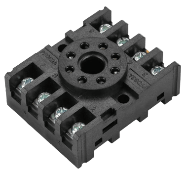
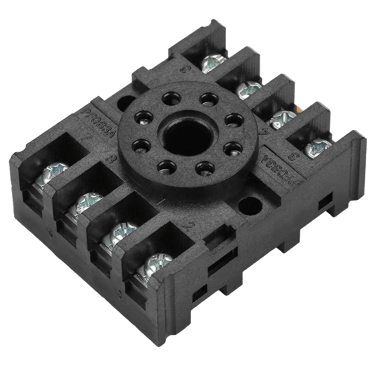
A relay base is a socket designed to hold a pin relay. It provides:
Mechanical support.
Electrical terminals for connecting control and load wiring.
Easy replacement of the relay without rewiring.
Secure locking mechanism to prevent vibration loosening.
Types of Relay Bases
DIN Rail Mount Base – Clips onto standard DIN rails in control panels.
Panel Mount Base – Bolted or screwed directly onto a panel.
PCB Mount Base – Designed for printed circuit boards.
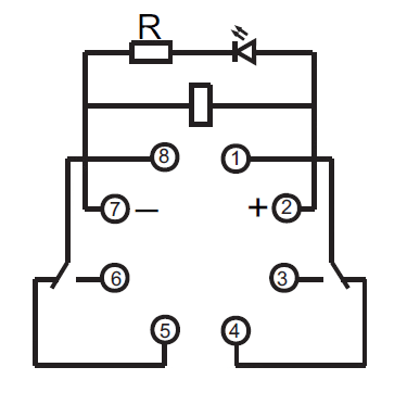
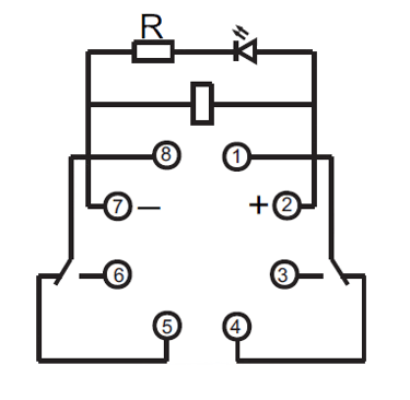
Pin Numbering and Wiring on the Base
Most relay bases have pin numbers printed or embossed for easy wiring. The pin numbering matches the relay’s datasheet.
For example, an 8-pin relay base:
Pins 2 & 7 – Coil connections.
Pins 1 & 3 – Common (COM) for pole 1.
Pins 4 & 5 – NO and NC for pole 1.
Pins 8 & 6 – NO and NC for pole 2.
(Pin numbering can differ depending on the manufacturer, so always check the datasheet.)
Advantages of Using a Relay Base
Quick replacement – No need to undo wiring; just pull out the old relay and insert a new one.
Better insulation – Reduces the risk of short circuits.
Standardisation – Accepts relays from multiple brands with the same pin layout.
Extra features – Some bases include built-in indicator LEDs or test buttons.
Practical Applications
Pin relays and bases are found in:
Motor starters.
Lighting control systems.
Industrial automation.
PLC (Programmable Logic Controller) output stages.
Home automation.
Automotive control systems (smaller versions).
Safety and Selection Tips
Match coil voltage – Using the wrong voltage can burn the coil or prevent operation.
Check contact rating – Ensure it can handle the load current and voltage.
Observe wiring diagrams – Each pin has a specific function.
Use proper base – Relay and base must match in pin count and layout.
Secure mounting – Prevents vibration from loosening connections.
Conclusion
A pin relay is a versatile and reliable switching device used in countless applications. Pairing it with the right relay base simplifies installation, improves maintenance, and ensures safe operation. By understanding the relay’s pin layout, how the coil works, and the role of the base, electricians and hobbyists can confidently integrate these devices into their projects.

Insights
Connect
david@elektreca.com
+254786927909
© 2025 Elektreca | Privacy Policy | Terms of Service | Disclaimer